

|
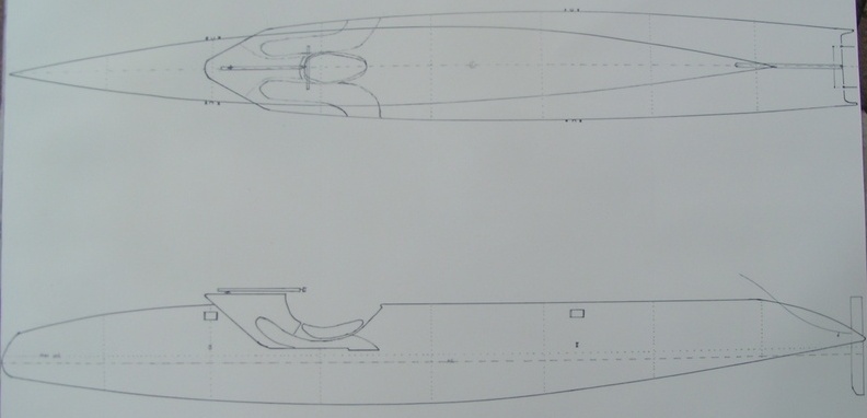
The main hull of the kite-sailer is the last component we build - as such expect a few changes / modifications along the way The general dimensions are : Length overall :32' Waterlength : 29' Max width at waterline : 36" Max width midship : 48" Draft : 18" Displacemnt empty : 0.9 t Max displacement : 1.5 t Construction : "Nidacore" core material with bi-axial carbon fiber in epoxy resin hand-laminated over the core in the interior and exterior surfaces till the waterline -Fiberglass cloth in the above waterline / cockpit area. Wave piercing deep bow area for maximum lateral resistance and minimum frontal resistance. Balancing the kite forces - while keeping him in line of sight Kite propulsion causes less heeling force than
using sail propulsion. Due to the lower distance between the CoG
and the center of pressure of the kite (the hauling point of the kite
on deck of the boat ) Open cockpit area for at least 6 passenger which give basic protection but would allow the use of paddles as alternative propulsion to approach sensitive wild life areas and not chase the birds away before you can actually see them.
Helms man control area - aft in
the main hull which should allow to control all navigation necessary
instruments and steer the course of teh kite-sailer. First step is to build and collect all the small custom build components for the main hull from the Harken track - to the seat and rudder blades ... |
Additional detail on the main hull :
Propulsion :
|
Most recent status :  |
|
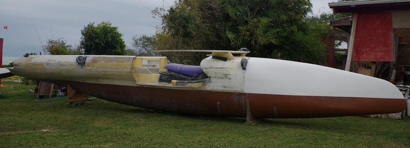
| November The main hull of the kite sailer is out of the shop and reset - The Amas need to get aligned and crossbeam attachment checked for alignment Winter will slow us down but we can start with the outfitting on the cold days and fairing on the warm days ...there is some light at the end of this tunnel ... |
 |
Oktober Interior divider get installed , laminated and faired before the first coat of epoxy primer will seal the surface from UV exposure ... As winter is approaching in South Texas our shop gets to cold for swift and proper cure .. Time to get the hull out of the shop and in the sunshine. |
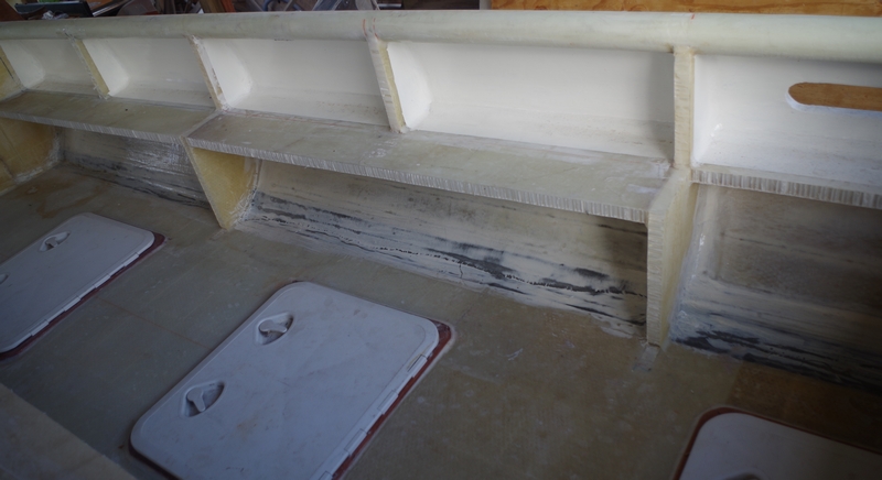 |
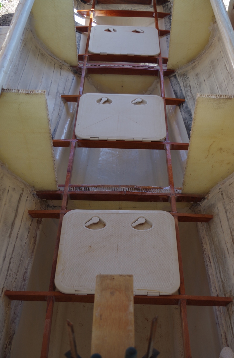
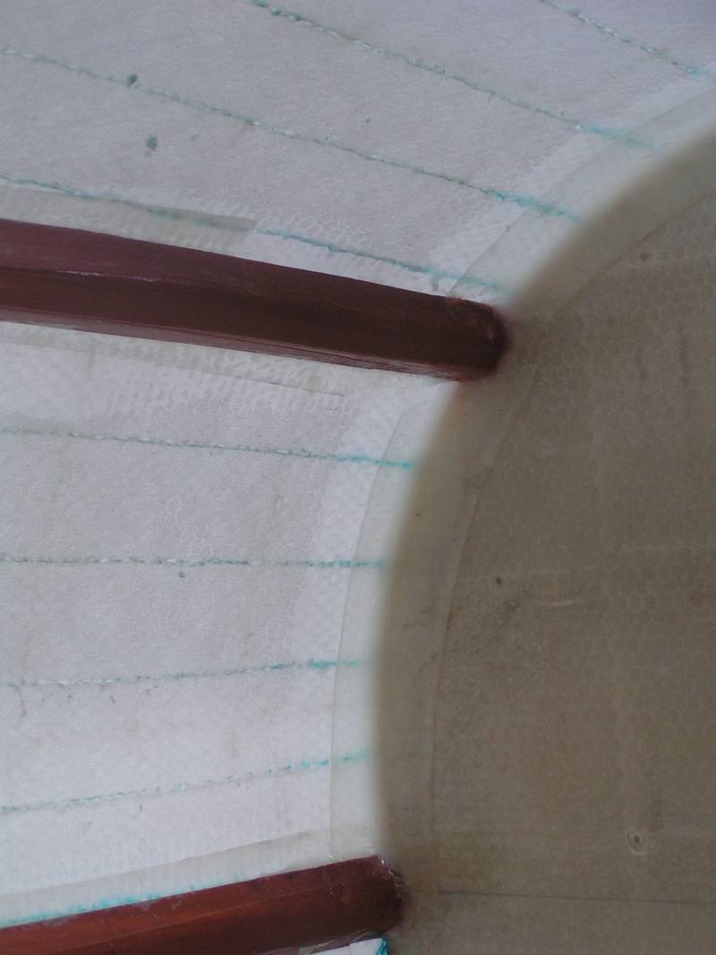
September The Nida core floor panels get laminated against the rib structure and cutouts for the inspection hatches installed. Bi-axial Carbon fiber along the hull joint and fiberglass cloth over the the core seal the surface and give the kite sailer the required stiffness in the water line. Since the deck has a curve all hatch joint surfaces need to get brought back to a leveled surface - first test of the hatches. The side walls get laminated in fiberglass cloth and we can step up to the interior components. |
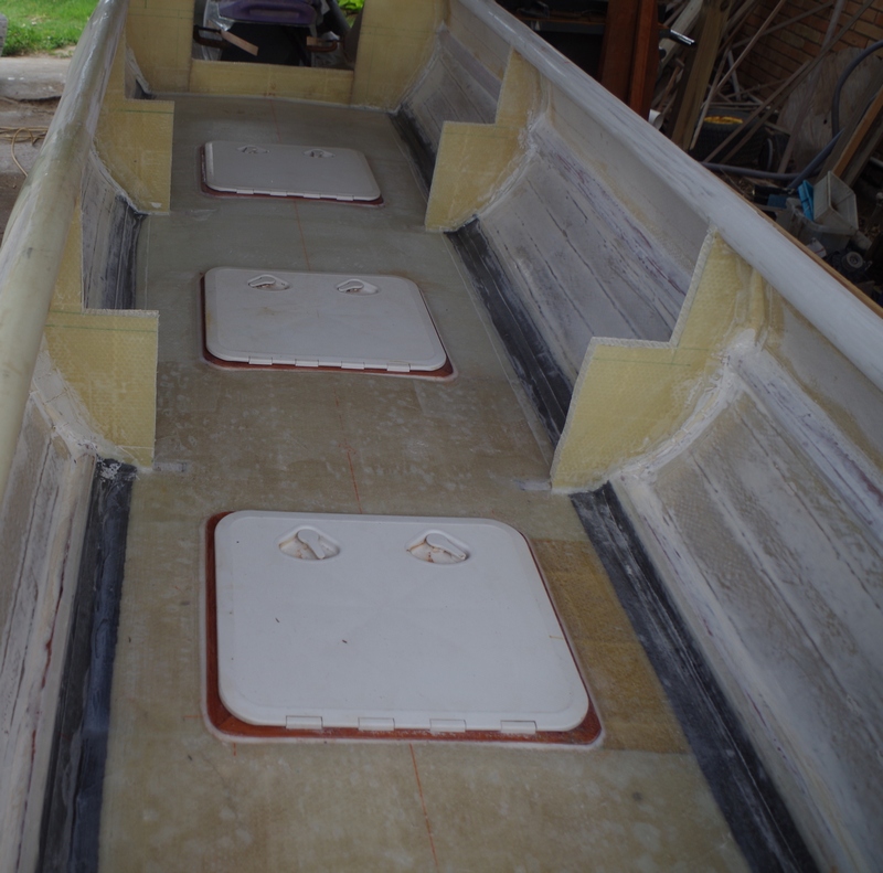 |
August The Kite-sailer has like any other boat floor supports which give the hull additional strength while providing the support for the access hatches. Theoretically we are ready for laying the Nidacore floor panels on the finished frame work ...it is time as we are in the middle of the hurricane season ... All supports get sealed with two applications of epoxy resin to seal any moisture out. |
 |
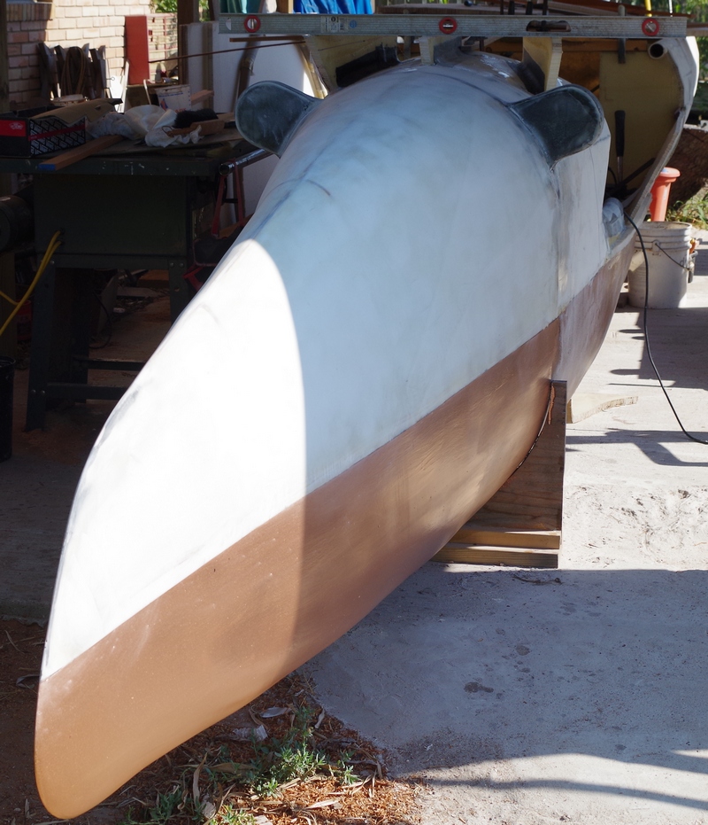
August After building the seat cowling we can install the forward crossbeam pivot points which should allow to lower or raise the crossbeams with stabilizer / floats or Amas according to sea and wind conditions . The stabilizer / floats or Amas are already finished and you can see their construction here : Also the support for the Kite controller track (bend sailing track) gets installed . This will allow the kite hauling point to run around the kite controller which keeps the kite always in direct line of sight and moves the kite hauling point to the right location on the deck of the kite sailer . The support for the Kite controller track is also the forward wave breaker support which will increase its strength without adding any further weight to the vessel . The first 8 feet of our Kite Boat are ready for the first application of epoxy primer ...looks like there is some light at the end of the tunnel .. |
 |
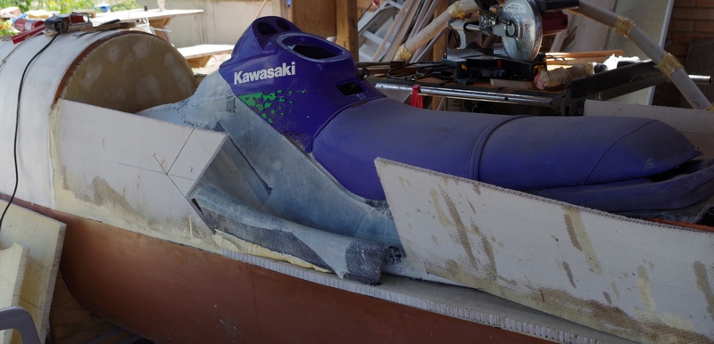
| July The first fit of the kite controller seat is like 4th of July fireworks ... so far so good all works out. The seat is a modified Kawasaki Jet ski body - build in carbon fiber .... Since the ergonomics of these skies allow a more or less comfortable ride - why shall we try to reinvent the wheel ... |
 |
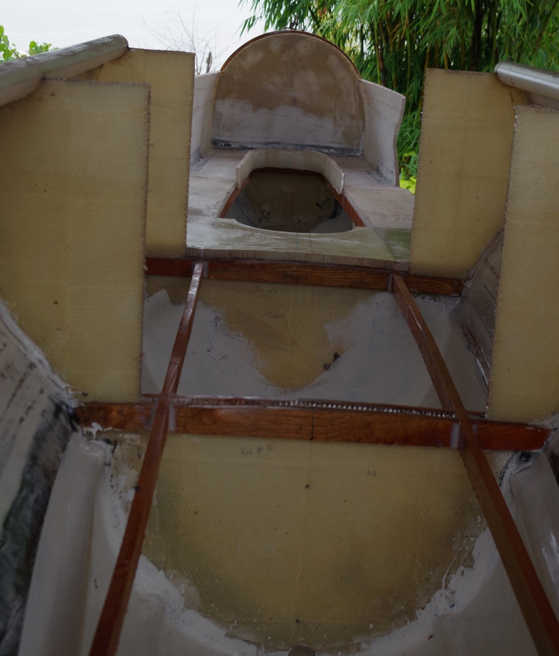
June The main floor stringer are getting installed as well as the base for the seat of the kite controller. It still looks a bit rough ... but so far the shape works out fine The floor boards get laminated to the hull with bi-axial carbon fiber which will give the hull the final strength extra impact support gets installed and we are off to take the part of the modified Jet ski. |
 |
May The finished bi-axial carbon fiber laminated hull provides a nice balance between strength and extreme low weight ... I have to admit that I am more than pleased ...after the laminate is finished the fairing and painting starts to make sure the core is properly protected for the next working step |
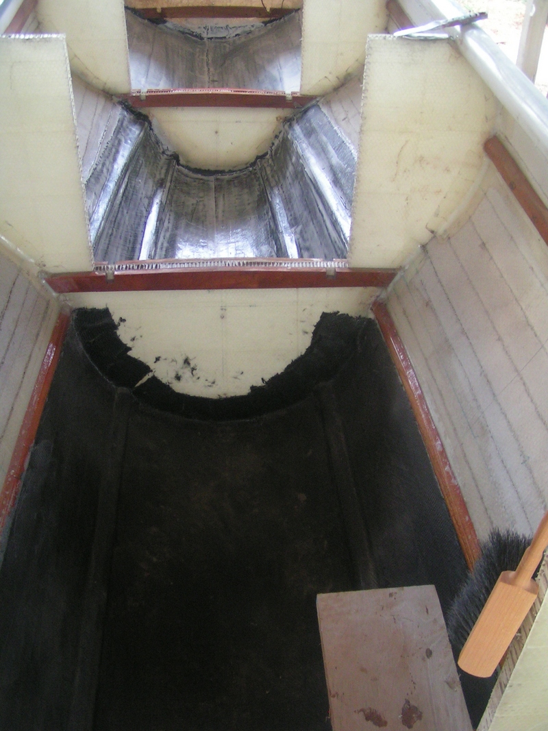 |
May After cleaning the hull well and making sure there are no wires from previous working steps the internal bi-axial carbon fiber cloth gets laminated in epoxy resin. The Spanish cedar stringer are under the laminate and provide a slight challenge to have good adhesion of the heavy cloth as such we lay in two sections with overlap in the keel area. |
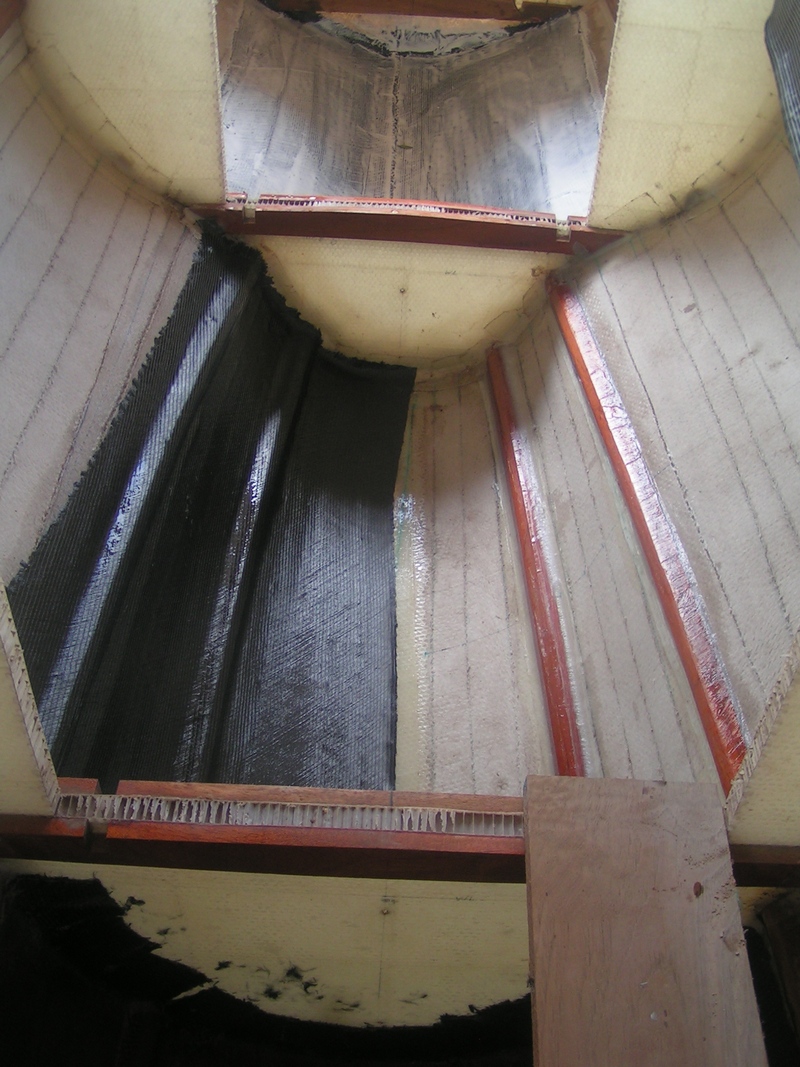 |
| April Once the hull was turned and secured we see the rest of the work ahead of us .. All the dust in the hull is now in the unprotected bilge - some cleaning and sealing the Nidacore core material will be the first priority ... Hope no rain will fall before that and soak in the core . |
 |
| April 3 weeks of preparation just to make sure the 3 seconds of the actual turn don't end up in a "ups" ...lol Challenge still was to lift the hull high enough so it can swing through without hitting the concrete or to turn before anticipated ...thereafter ...hope .. |
 |
| March
2013 During the winter season, progress slowed due to lower temperatures , as such it took longer than expected to fair the aft section and lay the carbon fiber - still we got that aspect finished as well and reached the point to lay the last layer of glass on the exterior and apply the first barrier / anti-fouling coat of copper poxy |
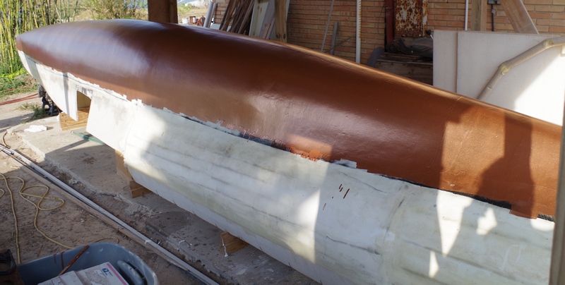 |
|
December After the bow area is finished for the final copper-poxy application we can concentrate ( as far as the weather will allow it ) on the stern section of the hull. We always wanted to try a jet drive on a sailer for a few reasons - No prop under the boat which gets fouled up , No outboard on the transom which puddles in the air if you go through a wave or comes out of the water in reverse, Smooth lines and smooth waterflow... But we expect certain drawbacks as Low reverse thrust Unit needs to be above the minimum water line and stay out of the water if at rest Some kind of intake duct to feed the water into the unit ... But all starts with getting first a jet unit installed into the hull as seen in the photo. Thereafter we will fair the hull and lay the carbon fiber |
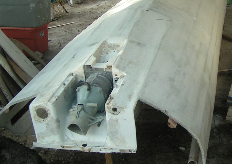 |
|
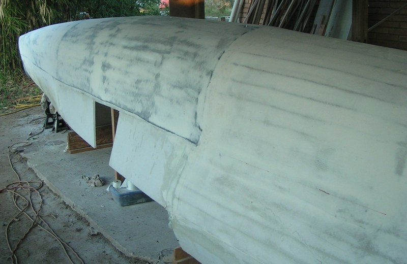
November Final fairing of the hull does not allow any power tools - perhaps a random orbit sander excluded and should take the last 1/8" imperfections out of the hull surface. Manual sanding-boards provide a better finish on the hull - are a bit more time consuming and require a high amount of muscle power but you will be a lot more pleased with the final lines of your hull. Do not sand into the carbon fiber strands - and if it helps add a small amount of tracer color into your fairing mix. Allow the fairing compound to cure full to ensure a easy surface to sand. |
 |
|
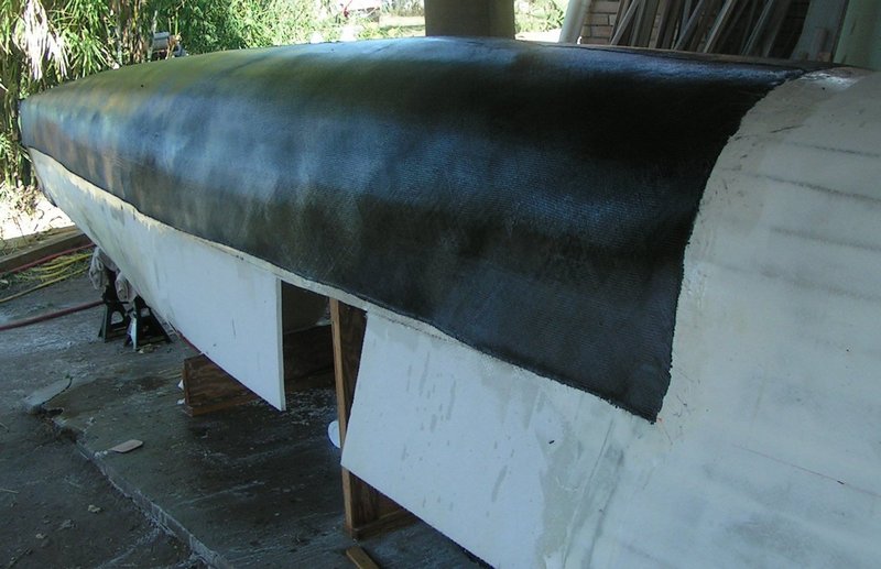
November The Kite-sailer is a composite hull where the skin carries the load as such it is important to have a perfect laminate on the outer bi-axial carbon fiber skin and inner bi-axial carbon fiber skin. In case you are on a similar project here some tips : sand the surface as smooth as possible and make sure you have no high spots. Brush the surface dust free and pressure wash the surface after sanding to make sure there is no sanding dust/contamination left on the surface. Let dry. Wipe the surface down with a clean shop-towel with Acetone. Do not use shop-towels which are brand new or washed with fabric softener ( Teflon based) . Make sure you have enough roller, brushes, squeegees, and shop towels within easy reach - Check for pinholes - if they are present ( which happens often after applying fairing ) apply the first coat of resin with Cabosil or solid Microballoons. Thereafter saturate the surface with resin - while unrolling the fabric, saturate the side facing the hull ( especially on heavy cloth as 10oz/sqy and up) - make sure the cloth is laying as smooth as possible on the hull surface before you saturate the outer surface. Apply resin to the outer surface and use the more flexible "Bondo" squeegees to distribute the resin equally over your cloth - allow 10 - 15 minuets for the resin to penetrate and follow with the stiffer polyethylene squeegees to force any excess resin out of the laminate. Watch for color / reflection change on your cloth to detect dry spots or over saturated sections - follow up for up to 1 hour before you should have a perfect laminate and allow the cure to proceed. Allow to cure for 2 - 4 hours ( or till the resin is cured to the point of a chewing gum feeling ) before laying a fairing ( Resin hollow Microballoons ) coat over the fabric to close the low spots in the fabric weave. Thereafter sit back and grab a beer ... yup you still have to clean up. |
 |
|
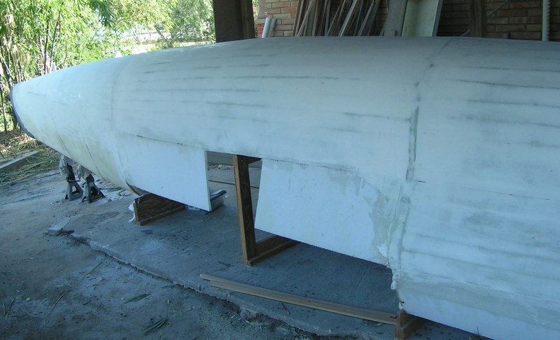
November After the initial fiberglass cloth on the core material - several layers of fairing take the edgy look / feel off the hull and created the smooth hull shape we desired. We decided to lay the carbon fiber in two sections - forward 16' and aft 16' just for simplicity and to make use of the currently still great weather conditions - the forward 16' are ready for the laminate - so lets get mixing.... |
 |
|
October Several layer of carbon fiber reinforce the bow section - as we want a smooth sailing through the waves and some resistance against the basic obstacles on our journey. The lines from forward facing aft line up nicely and after several layers of fairing we we can start to apply the carbon fiber in the underwater ship. |
|
|
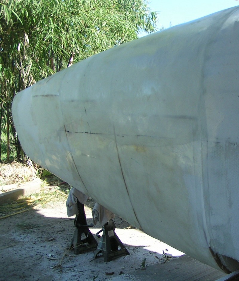
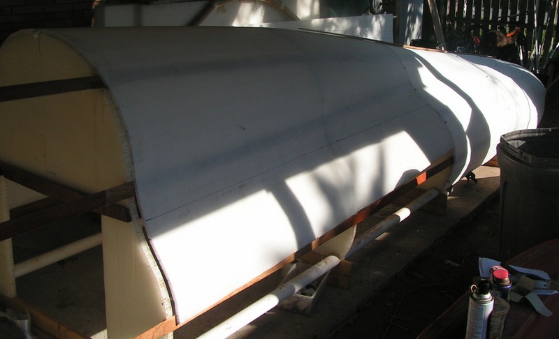
October The previous prepared bow foam core gets laminated to the Nidacore hull / bow rib and the primary fairing process can start.The Nidacore hull gets the first layer of fiberglass cloth in epoxy resin before the initial fairing gets applied to take the "edge" off the core panels. We want the hull 80% smooth before laying the outer bi-axial carbon fiber skin. As winter is approaching so does the cure time of the resin require more time. |
 |
|
October
|
 |
|
September
|
< |
|
September |
|
|
September
|
 |
|
September |
 |
|
August
|
 |
|
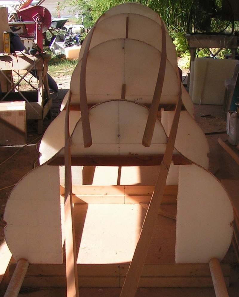
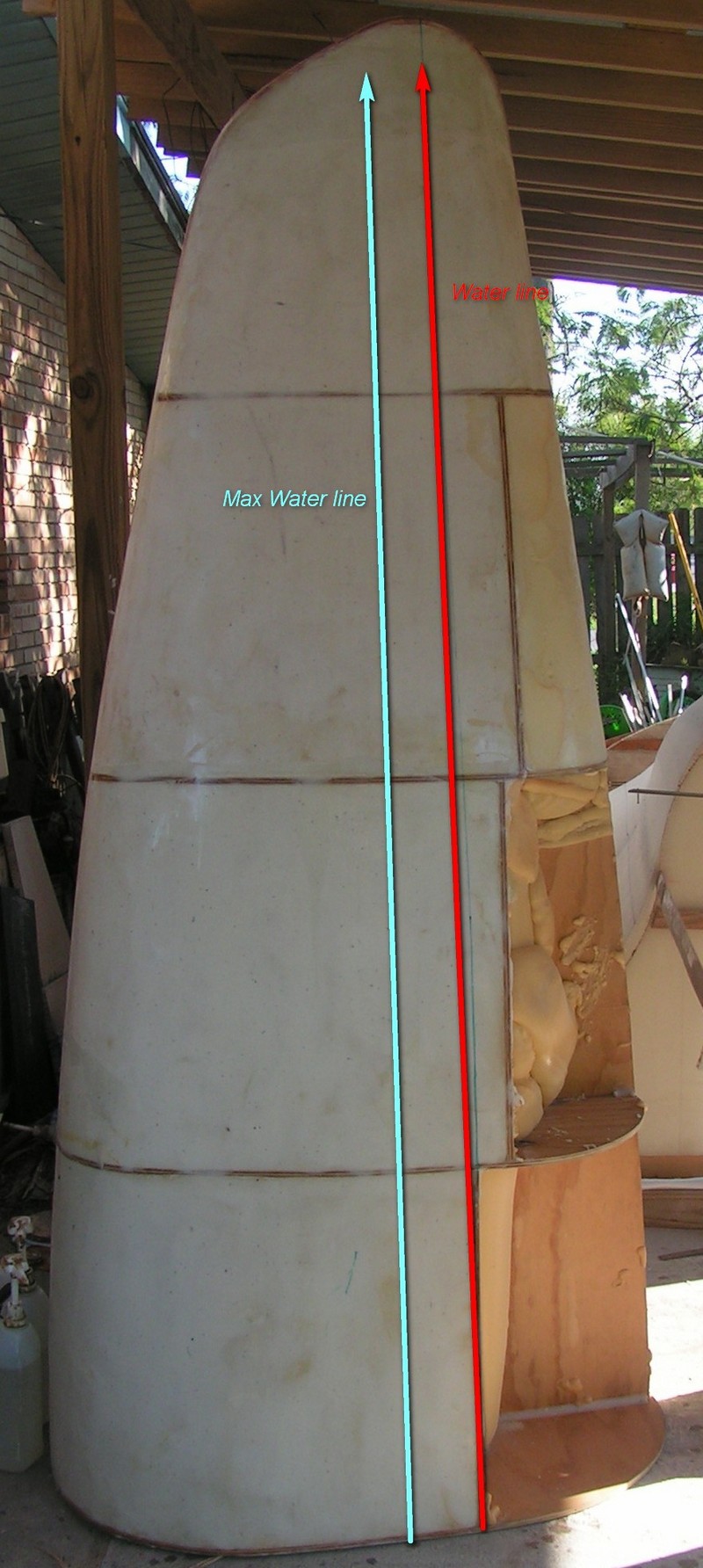
July The foam core gets shaped and
sealed with a epoxy / CAB-O-SIL Fumed Silica putty - sanded and
laminated in fiberglass cloth . |
 |
|
July
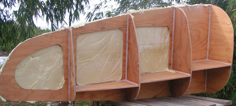
The bow section of the
kite-sailer is a solid urethane foam core with a internal ply rib
structure - we hope that in the worse case scenario it will
absorb impact or break / crush.
|
 |
© 2012-2015 kite-sailer.com